Writing /var/www/alexforencich.com/wiki/data/cache/d/d6d3e1a94debd48eade0926522a585d9.xhtml failed
Nixie Clock
Introduction
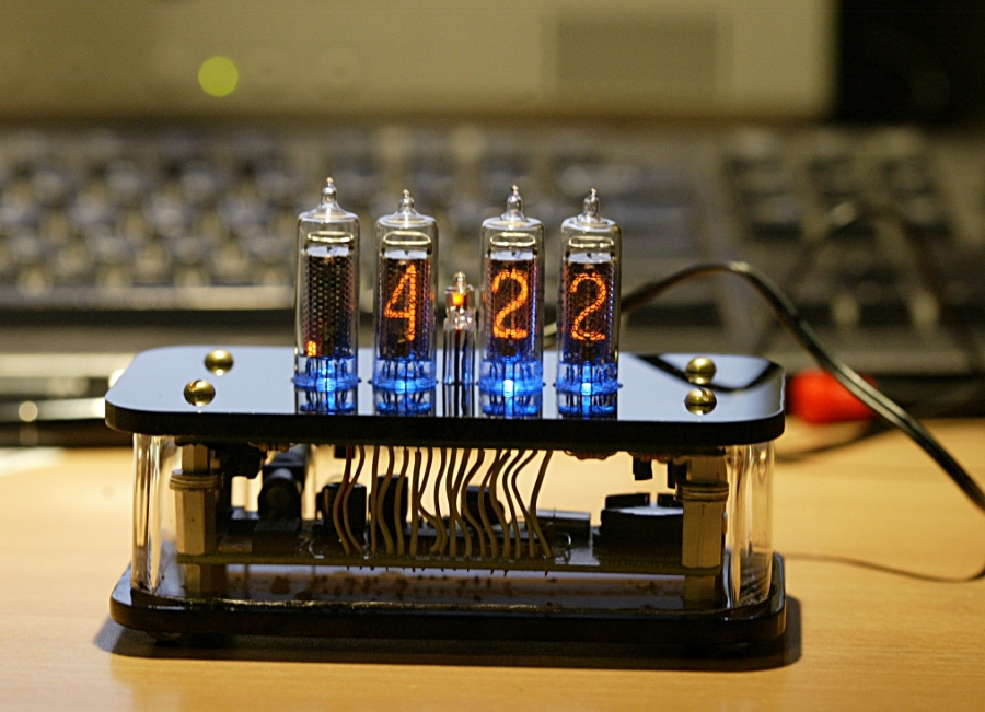
I designed and built this basic 4 tube nixie clock in my senior year of high school.
For more a detailed introduction, please read the Nixie Clock: History page.
Detailed Information
Specifications
- Display
- 4x ИН-16 (IN-16) Nixie tubes
- 208V anode bias
- 1x К155ИД1 (K155ID1) high voltage BCD to decimal decoder/nixie tube driver (74141 equivalent)
- Processor
- Microchip PIC18F2550-I/SO
- 20 MHz clock, 5 MIPS
- 32K Flash
- 2K RAM
- 10x 10-bit ADC
- I²C, SPI, and EUSART peripherals
- Clock
- Maxim/Dallas DS1340C
- I²C Interface
- Built-in crystal
- Backup battery support
- Power Supply
- Input: 12V DC
- Output: 5V DC
- 7805 regulator
- High Voltage Power Supply
- Input: 12V DC
- Output: 12V - 300V DC variable
- Boost topology
- IRF720 400V 3.3A N-channel MOSFET
- HER105 400V 1A fast recovery rectifier
- 4.7µH Inductor
